Robert F. Bourque, Ph. D., P.E.
Bourque Engineering LLC
Los Alamos, New Mexico USA
bob@rfbourque.net
505-412-0194
Chapter |
Title |
1 |
|
2 |
|
3 |
|
4 |
|
5 |
|
6 |
|
7 |
|
8 |
|
9 |
|
10 |
|
11 |
|
12 |
|
13 |
|
14 |
|
15 |
|
16 |
|
17 |
|
18 |
|
19 |
|
20 |
|
21 |
|
|
|
|
|
|
A Compact Pollution-Free
External Combustion Engine
with High Part-Load Efficiency
Previous Chapter | Next Chapter
12. Expander Hot Cylinder Lubrication
The key uncertainty in the entire engine is the hot cylinder and its lubrication, which will require experiments. Even the highest quality oils cannot take the high time-average temperatures. They range from about 540ºC (1000ºF) on the cylinder wall, to 590ºC (1100ºF) in the Expander inlet steam, to up to 650ºC (1200ºF) should the lubricant contact the inside walls of the Steam Generator tubes. Therefore the cylinders are lubricated by a combination of powdered high-temperature lubricant, cylinder sleeves impregnated with these lubricants, and hard surface coatings. Figure 12 shows the general arrangement.
NASA did pioneering work on high-temperature lubricants at the beginning of the space program [16]. Lubricants they identified, such as calcium fluoride, lead oxide, and boric oxide are possible candidates here. There are others, which are discussed below.
The first dry lubricant to be examined will likely be graphite powder and graphitized metals [17]. Graphite lubricity requires water or water vapor, which is in abundance here. Fine graphite powder would circulate through the entire steam circuit. Key issues are degradation in the hot steam and clumping in the Feedpump.
Other powdered lubricants also look promising. These include tungsten disulfide (WS2), selenium disulfide (SeS2) and hexagonal boron nitride (hBN). These materials have very high temperature capability and low friction [18]. They can be used alone or in combination [19,20].
There are a variety of hard surface coatings that can be used in conjunction with dry lubricants. These include nickel-boron [21], special chrome platings [22], and titanium carbide or tungsten carbide [23].
The above are just examples of available dry lubricants and wear-resistant coatings. There are other options and a well-established industry available for assistance. This is a selection task, not a research task.
|
|
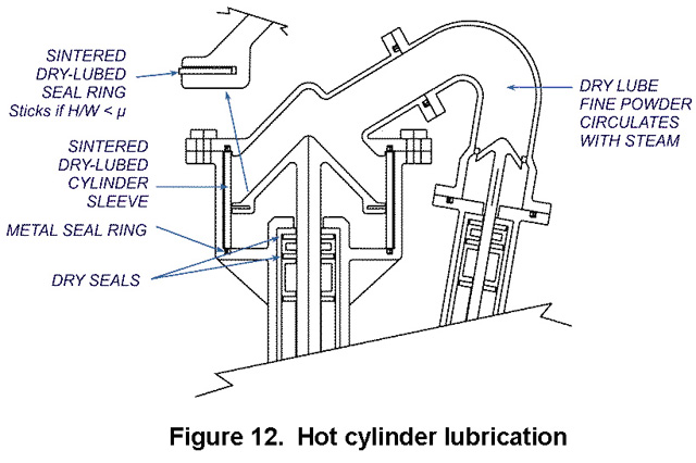
The use of dry rather than liquid lubricants allows one to exploit the fact that static friction is then greater than sliding. Figure 12 shows how this can be used to reduce seal wear. The primary seal ring, on the periphery of the piston, is deliberately thin (leakage just vents to the next stage). Forces from steam pressure keep it from moving provided its height-to-width ratio is less than the static friction coefficient. Therefore, the seal is stuck in position when there is a differential pressure across the piston, as occurs during the power stroke. The seal then essentially skims along the cylinder wall without wearing. It resets itself only when there is no pressure difference and hence no leakage, that is, during the exhaust stroke. A small spring provides the resetting force.
There are a number of options for the seal itself. One has been patented by the author [24].