Robert F. Bourque, Ph. D., P.E.
Bourque Engineering LLC
Los Alamos, New Mexico USA
bob@rfbourque.net
505-412-0194
Chapter |
Title |
1 |
|
2 |
|
3 |
|
4 |
|
5 |
|
6 |
|
7 |
|
8 |
|
9 |
|
10 |
|
11 |
|
12 |
|
13 |
|
14 |
|
15 |
|
16 |
|
17 |
|
18 |
|
19 |
|
20 |
|
21 |
|
|
|
|
|
|
A Compact Pollution-Free
External Combustion Engine
with High Part-Load Efficiency
Previous Chapter | Next Chapter
14. Two More Engine and Vehicle Examples
Engines have been sized from 22 kW (30 hp), for a “personal urban car” to 2400 kW (3200 hp) for a locomotive. Two more examples from this database are presented below.
|
|
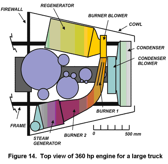
The first, shown in Figure 14, is for a semi-truck with 36,000 kg (80,000 lb) gross weight, the maximum allowed on US highways. The engine produces 268 kW (360 hp) at 3600 rpm. The Expander cylinder heads and valves are in light purple (the first stage is hidden under the Burner). As seen, the last Expander stage seems a bit large and can probably be divided in two. The reason for the large size is that the stroke for all stages is the same. Perhaps this feature can be modified in the future for large engines. Note that the condenser readily fits in the existing radiator space.
|
|
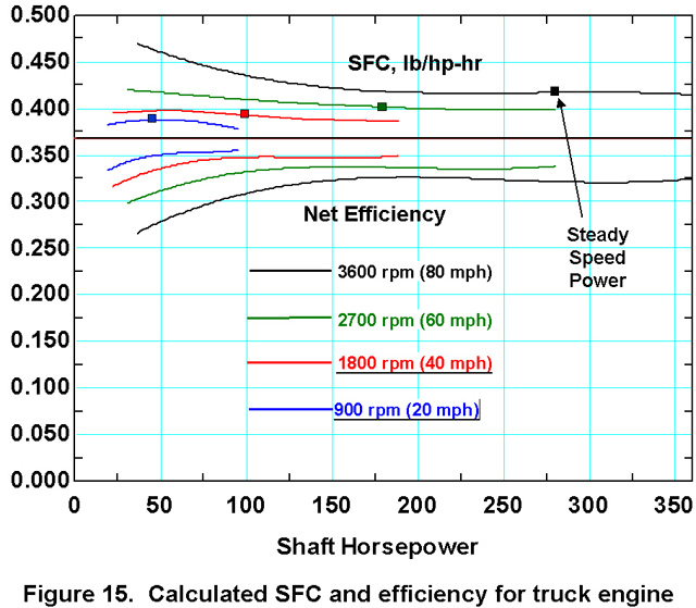
The calculated specific fuel consumption and net efficiency are shown in Figure 15. There is relatively more room in this truck engine compartment than in smaller vehicles. Therefore one can enlarge the heat exchangers, which reduces pressure drops through them, and use a lower condensing temperature. All this increases efficiency.
The four points shown in the SFC plots are the steady-speed power values needed for this vehicle and indicate SFC values actually accessed during driving. They come fairly close to modern diesel engines. Calculated fuel economy for this 80,000 lb rig with diesel fuel is a nominal 2.6 km/liter (6 mpg) at 97 km/hour (60 mph), about the same as existing rigs.
The second example is a 63 kW (85 hp) engine in a Saab 96 (990 kg/2180 lb including fuel and driver). This popular front-wheel drive car, often used in rallies, was built from 1960 to 1980. Its measured CD is 0.32, not far above the best sedans today. Despite the light weight, it had excellent crashworthyness and could carry four full-size adults with luggage. A modern version would be an ideal compact car.
|
|
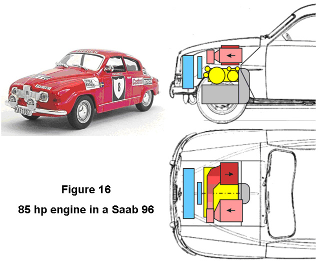
The engine installation is shown in Figure 16. Here the Expander (in yellow) is horizontally opposed and mounted over the existing fore-and-aft transaxle (purple). The Regenerator (pink) and Steam Generator (red) are mounted side-by-side over the Expander. Table 4 shows some of the calculated performance:
|
|
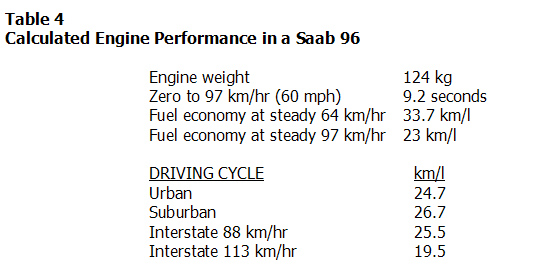
This spectacular performance results from the light weight, low drag coefficient and small frontal area of the vehicle, and from the high net efficiency of the engine at normal power settings.